Verilog Code for 4:1 Multiplexer in different styles

 AIM:  To develop HDL Program for 4:1 Multiplexer in different styles


Tools/Software Required:

1.                                                         Personal Computer.

2.                                                         Vivado 2019.2 Software

3.                                                         Verilog

Procedure:

1.                  Click on Vivado2017.2 icon.A window is opened.

2.                  Click on File→New Project→Press Next→Give the Project name and Project Location→Press Next→Choose Project Type as RTL Project→Press Next→

3.                  Create File→File Type: VHDL\VERILOG File Name→ Filename→Press Next→ Press Next→ Press Next→Finish.

4.                  Write the module definition by giving input ports and output ports  Press Ok.

5.                  Two workspaces are opened with names Project Manager and Flow Navigator

6.                  In Project Manager  Click on Sources →Design Sources→File→A window is opened with File name. Write the Program in the File Click on Save.

7.                  In Flow Navigator→Click on Simulation  →Run Simulation→Run Behavioural Simulation→A window is opened with name “untitled1”→Force Constants→Run for 100 µs. Observe the simulation results for various combinations by clicking on Zoom Out.

Verilog Code for 4:1 Multiplexer


Data flow Modelling
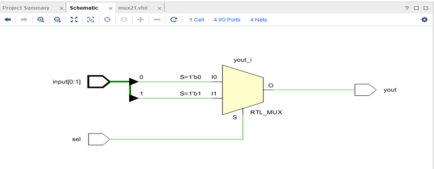

module mux41(
    input a,b,c,d,
    input s1,s0,
    output y
    );
    assign y=s1?(s0?d:c):(s0?b:a);
endmodule


        Behavioural Modelling
        Version 1:

      module mux41b(
    input a,b,c,d,s1,s0,
    output  reg y
    );
   
    always @(*)
    begin
    if (s1)
    begin
    if(s0)
    y=d;
    else y=c;
    end
    else 
    begin
    if (s0)    y=b;
    else y=a;
    end
    end
endmodule
  Version 2:
   module mux41d(
    input [3:0] i,
    input [1:0] s,
    output reg y
    );

always @ (*)
begin

case (s)
2'b00 : y <= i[0];
2'b01 : y <= i[1];
2'b10 : y <= i[2];
2'b11 : y <= i[3];

endcase

end

endmodule  
    

      Gate Level  Modelling
      module mux41c(
    input i0,i1,i2,i3,s1,s0,
    output y
    );
    wire s1b,s0b,a,b,c,d;
    not (s1b,s1);
    not (s0b,s0);
    and (a,s1b,s0b,i0);
    and (b,s1b,s0,i1);
    and (c,s1,s0b,i2);
    and (d,s1,s0,i3);
    or (y,a,b,c,d);
endmodule

Comments

Popular posts from this blog

MULTIPLEXER

Decoder

Realization of Logic gates using Hardware Description Language