MULTIPLEXER
Multiplexer
AIM: Develop HDL Program for 2:1 Multiplexer, 4:1 Multiplexer, 8:1
multiplexer, 16:1 multiplexer
Tools/Software Required:
1.
Personal Computer.
2.
Vivado 2019.2 Software
3.
Verilog/VHDL
THEORY:
Multiplexer generally means many into one. A
multiplexer is a circuit with many Inputs but only one output. By applying
control signals we can steer any input to the output. The circuit has n-input
signal, control signal & one output signal. Where 2n= m. One of the popular
multiplexer is the 16 to 1 multiplexer, which has 16 input bits, 4 control bits
& 1 output bit. Multiplexer (or mux) is a device that selects one of
several analog or digital input signals and forwards the selected input into a
single line. A multiplexer of 2n inputs has n select lines, which are used to
select which input line to send to the output. An electronic multiplexer can be
considered as a multiple-input, single-output switch. Multiplexers are mainly
used to increase the amount of data that can be sent over the network within a
certain amount of time and bandwidth. A multiplexer is also called a data
selector
Procedure:
1.
Click on Vivado2017.2 icon.A window is opened.
2.
Click on File→New Project→Press Next→Give the Project name and Project
Location→Press Next→Choose Project Type as RTL Project→Press
Next→
3.
Create File→File Type: VHDL\VERILOG File Name→ Filename→Press
Next→ Press Next→ Press Next→Finish.
4.
Write the module definition by giving input ports and output
ports →Press Ok.
5.
Two workspaces are opened with names Project Manager and Flow Navigator
6.
In Project Manager →Click on Sources →Design Sources→File→A window is opened
with File name. Write the Program in the File →Click on Save.
7.
In Flow Navigator→Click on Simulation →Run Simulation→Run Behavioural
Simulation→A window is opened with name “untitled1”→Force Constants→Run
for 100 µs. Observe the simulation results for various combinations by
clicking on Zoom Out.
VHDL Code for 2:1 Multiplexer
library IEEE;
use IEEE.STD_LOGIC_1164.ALL;
entity mux21 is
Port ( sel : in STD_LOGIC;
input :
in STD_LOGIC_VECTOR (0 to 1);
yout :
out STD_LOGIC);
end mux21;
architecture Behavioral of mux21 is
begin
process(input,sel)
begin
case(sel) is
when '0' => yout <= input(0);
when '1' => yout <= input(1);
when others=> null;
end case;
end process;
end Behavioral;
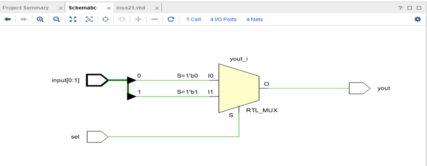
RTL Schematic for 2:1 Multiplexer
Simulation Waveform for 2:1 Multiplexer

Verilog Code for 2:1 Multiplexer
//2x1 MUX
module muxx2x1( A, B, S, Z);
input wire A, B, S;
output reg Z;
always @(A or B or S)
begin
if(S)
Z= B;
else
Z=A;
end
endmodule
RTL SCHEMATIC for 2:1 Multiplexer

Simulation Waveform for 2:1 Multiplexer

VHDL Code for 4:1 Multiplexer
library IEEE;
use IEEE.STD_LOGIC_1164.ALL;
entity mux41 is
Port ( input : in STD_LOGIC_VECTOR (0 to 3);
sel : in
STD_LOGIC_VECTOR (0 to 1);
yout :
out STD_LOGIC);
end mux41;
architecture Behavioral of mux41 is
begin
process(input,sel)
begin
case(sel) is
when "00" => yout<=input(0);
when "01" => yout<=input(1);
when "10" => yout<=input(2);
when "11" => yout<=input(3);
when others=>null;
end case;
end process;
end Behavioral;
RTL Schematics for 4:1 Multiplexer

Simulation Waveform for 4:1 Multiplexer

Verilog code for 4:1 MUX using 2:1 MUX
module muxx4x1(A,B,C,D,S0,S1,S2,Z);
input
A,B,C,D,S0,S1,S2;
output Z;
wire y0,y1;
muxx2x1
x1(A,B,S0,y0);
muxx2x1
x2(C,D,S1,y1);
muxx2x1
x3(y0,y1,S2,Z);
endmodule
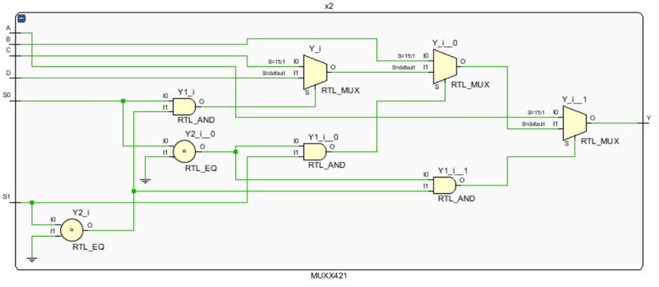
RTL SCHEMATICS for 4:1 Multiplexer

Simulation Waveform for 4:1 Multiplexer

Verilog
Code for 4:1 Multiplexer
module MUXX421(A,B,C,D,S0,S1,Y);
input wire
A,B,C,D,S0,S1;
output reg
Y;
always @(A or B or C or D or S0 or S1)
begin
if(S0==0 && S1==0)
Y= A;
else if(S0==0 && S1==1)
Y=B;
else if(S0==1 && S1==0)
Y=C;
else
Y=D;
end
endmodule
RTL Schematic for 4:1 Multiplexer

Simulation Waveform for 4:1 Multiplexer

VHDL Code for 8:1 Multiplexer
library IEEE;
use IEEE.STD_LOGIC_1164.ALL;
entity mux81 is
Port ( inp : in STD_LOGIC_VECTOR (0 to 7);
sec : in
STD_LOGIC_VECTOR (0 to 2);
yout :
out STD_LOGIC);
end mux81;
architecture Behavioral of mux81 is
begin
process(inp,sec)
begin
case (sec) is
when "000" => yout<=inp(0);
when "001" => yout<=inp(1);
when "010" => yout<=inp(2);
when "011" => yout<=inp(3);
when "100" => yout<=inp(4);
when "101" => yout<=inp(5);
when "110" => yout<=inp(6);
when "111" => yout<=inp(7);
when others=>null;
end case;
end process;
end Behavioral;
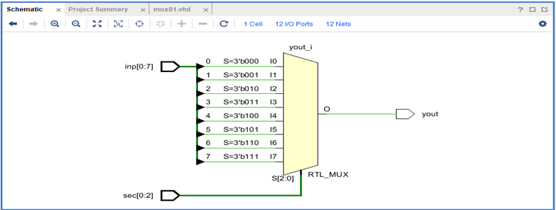
RTL Schematics for 8:1 Multiplexer
Simulation Waveform for 8:1 Multiplexer
Verilog program for 8:1
Multiplexer
module muxx8x1(d0,d1,d2,d3,d4,d5,d6,d7,sel,out);
input d0,d1,d2,d3,d4,d5,d6,d7;
input [2:0] sel;
output reg out;
always@(sel)
begin
case(sel)
3'b000:out=d0;
3'b001:out=d1;
3'b010:out=d2;
3'b011:out=d3;
3'b100:out=d4;
3'b101:out=d5;
3'b110:out=d6;
3'b111:out=d7;
endcase
end
endmodule
RTL Schematic for 8:1
Multiplexer

Simulation Waveform for 8:1
Multiplexer

VHDL Code for 16:1 Multiplexer
library IEEE;
use IEEE.STD_LOGIC_1164.ALL;
entity mux161 is
Port ( inp : in STD_LOGIC_VECTOR (0 to 15);
sel : in
STD_LOGIC_VECTOR (0 to 3);
yout :
out STD_LOGIC);
end mux161;
architecture Behavioral of mux161 is
begin
process(inp,sel)
begin
case (sel) is
when "0000" => yout<=inp(0);
when "0001" => yout<=inp(1);
when "0010" => yout<=inp(2);
when "0011" => yout<=inp(3);
when "0100" => yout<=inp(4);
when "0101" => yout<=inp(5);
when "0110" => yout<=inp(6);
when "0111" => yout<=inp(7);
when "1000" => yout<=inp(8);
when "1001" => yout<=inp(9);
when "1010" => yout<=inp(10);
when "1011" => yout<=inp(11);
when "1100" => yout<=inp(12);
when "1101" => yout<=inp(13);
when "1110" => yout<=inp(14);
when "1111" => yout<=inp(15);
when others=>null;
end case;
end process;
end Behavioral;
RTL Schematic for 16:1 Multiplexer

Simulation Waveform for 16:1 Multiplexer
Verilog code for 16:1 MUX
using 4:1 MUX
module muxx16x1(A,S,Z);
input
[1:16]A;
input
[1:10]S;
output Z;
wire
y1,y2,y3,y4;
MUXX421
x1(A[1],A[2],A[3],A[4],S[1],S[2],y1);
MUXX421
x2(A[5],A[6],A[7],A[8],S[3],S[4],y2);
MUXX421
x3(A[9],A[10],A[11],A[12],S[5],S[6],y3);
MUXX421
x4(A[13],A[14],A[15],A[16],S[7],S[8],y4);
MUXX421
x5(y1,y2,y3,y4,S[9],S[10],Z);
endmodule
RTL Schematic for 16:1 Multiplexer

RTL Schematic for 2:1 Multiplexer Coined as “MUXX421” in 16:1
Multiplexer
Simulation Waveform for 16:1 Multiplexer

Result:
The 2:1,4:1,8:1,16:1 Multiplexers are simulated using Vivado2017.2 software
on an I3 Processor with 64-bit Operating System.


Comments
Post a Comment